Filter Bank Method
This module allows you to measure noise in frequency bands of different widths: Octave, Third Octave, Deci-Decade, Decade, 1/10 Octave, and 1/12 Octave. These measurements are compatible with the ANSI Standard ANSI S1.11-2004 American National Standard Specification for Octave-Band and Fractional-Octave-Band Analog and Digital Filters.
The method works by first measuring noise noise bands the highest octave of the available data using a bank of band pass filters. The data are then decimated by a factor 2 (or 10 for Decade bands) and a further set of measurements made in the next octave down (i.e. the highest octave of the decimated data). This process can be repeated for as many decimators / octaves of data that you wish, reaching lower and lower frequencies. Because the amount of raw data to be processed is halved in each decimator, each bank of filters requires increasingly less processing power.
Creating the module
From the File>Add modules>Sound Processing menu, or from the pop-up menu on the data model display select ” Noise Band Monitor”. Enter a name for the new module and press Ok.
Configuring the module
To configure the module, open the settings dialog from the Detection>“your module name” menu:
Raw Data Source
Select a source of raw data. This will generally be a Sound Acquisition Module or the output of a Decimator if a lower frequency noise measurement is required. Check the channels you want to measure noise on.
Output Interval
Enter the interval between measurements in seconds.
Measurement Bands
Select the band type you wish to measure in from the drop down list, and the Reference Frequency, which is the centre frequency of a band, against which all other band centres will be calculated. By default, this is 1000Hz.
Select the maximum and minimum frequencies you want to measure between. Bands will then be calculated to fit between these limits, i.e. the upper edge of the highest band will not be greater than the maximum frequency and the lower edge of the lowest band will not be lower than the minimum frequency. e.g. if you are working with third octave bands and set the frequency limits to be 200Hz and 24kHz, you’ll get 20 bands between 222.7Hz and 22.63kHz.
Filters
Select Butterworth or IIR Filters. Generally, Butterworth filters will operate much faster than FIR filters on a desktop computer. Generally 6th order Butterworth or 7th order (128 tap) FIR filters are more than adequate. The exact cut off frequencies and filter responses are shown for information only.
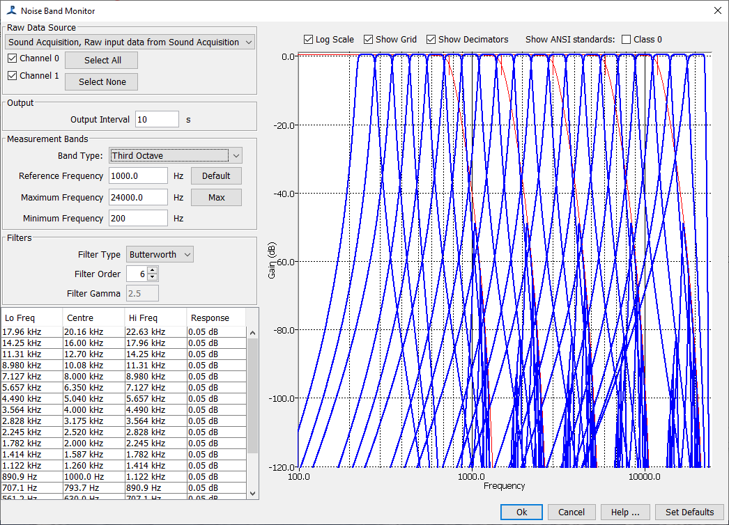
Bode Plots
The filter responses and the responses of the decimators are shown in the Bode plot on the right hand side of the dialog. It is also possible to overlay the various ANSI standards. The scale of the amplitude axis can be altered by double clicking on it.