Configuring
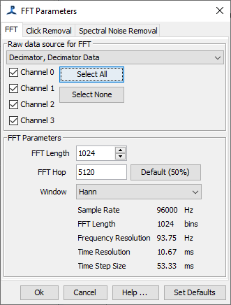
The FFT Parameters dialog is shown automatically when a new FFT Engine is created. It can also be accessed in the two following ways
1. From the Detection>FFT Parameters… menu
2. From the pop-up menu on the FFT Engine window in the PAMGuard Data Model display.
Select a data source
From the drop down list select a source of audio data. When you select a new data source, the channel list will be updated to show the number of channels in the selected data source. Tick the check boxes for the channels you wish FFT data to be computed for.
To save processor power, do not calculate FFT data for channels that are not needed in subsequent PAMGuard processes.
Set the FFT Length and Hop
The FFT algorithm is most efficient when the FFT length in samples is an exact power of 2, e.g. 256, 512, 1024, 2048, etc. However modern FFT algorithms can handle other FFT lengths if you really want them. For instance, if you have data sampled at 1000Hz and really want your FFT’s to be exactly 1/4 second long, you could chose a FFT length of 250 samples instead of 256. Non power of 2 FFT lengths will be fine with low frequency data, but if you’re processing high frequency data, we’d recommend that you maximise efficiency by sticking to powers of 2!
The little arrows to the right of the FFT Length field can be used to increment / decrement the length by powers of 2. For other values, simply type in what you want.
The FFT Hop is the number of samples between the start of successive FFT blocks - often this is set to half the FFT length to provide overlap. Some people like more overlap, since it can give a smoother display, however this is generally only introducing redundancy into the data and is not efficient.
Generally, you wouldn’t set the FFT Hop to be greater than the FFT Length, since that would mean that some data are never used. However, for simple diagnostics, such as an LTSA, it can be useful to have a bigger hop size since the FFT Engine would use less CPU and the LTSA would still be a good diagnostic tool to show background noise levels and demonstrate that channels are working.
When configuring the FFT engine, it is important to think about the time and frequency resolution of the data you’re generating. The frequency resolution of the data is the sample rate divided by the FFT length, and the time resolution is the exact opposite, namely the FFT length divided by the sample rate. So if you pick a big FFT length, you’ll get really find frequency resolution, but poor time resolution and if you pick a small FFT length, you’ll get poor frequency resolution, but excellent time resolution. Think about the types of sounds you’ll be detecting, or viewing on displays using the FFT data. Generally, it’s helpful if the sounds are spread in both time AND frequency. For example, in the figures below the same right whale upsweep sounds are shown with three different FFT lengths.
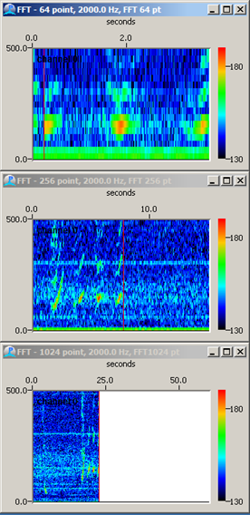
In the top image, the FFT length is too short, so the calls are well spread out in time, but there is little frequency information. In the bottom display, the FFT length is too long, so there is excellent frequency resolution, but in time the calls are compressed into a single pixel of the display. The central panel has got it about right, the 256 point FFT giving a frequency resolution of 7.8 Hz, and a time resolution of 128ms - perfect for a call that lasts nearly a second and sweeps from 100 to 200Hz.
Set the Window type
Select a windowing function from the following options:
Rectangular
Hamming
Hann (default)
Bartlett (Triangular)
Blackman
Blackman-Harris
The Hann window will be fine for most purposes. If you want to learn more, see Wikipedia.